UNITED STATES
PATENT
OFFICE.
OTTO
LILIENTHAL, OF BERLIN, GERMANY.
FLYING-MACHINE.
SPECIFICATION forming part of Letters Patent No.
544,816, dated August 20, 1895
Application filed February 28, 1894. Serial No. 501,880.
(No model.)
To all whom it may concern:
Be it known that I, OTTO
LILIENTHAL, manufacturer, a subject of the
German Emperor, and a resident of Berlin, German Empire, have invented
certain new and useful Improvements in Flying-Machines, of which the
following is a specification.
This invention relates to
flying-machines which resemble in their
construction the structure of birds' wings. The object of these
flying-machines is to imitate the soaring of birds as well as their
ordinary flight, which is effected by the flapping of the wings. The
improved machine comprises two wings, which, after the manner of birds'
wings, are slightly valued upward. These wings are fixed by two rods
laid crosswise one upon the other and firmly connected together, which
rods form a carrying-frame or part of a carrying-frame to which the
person intending to fly may hold, so as to be suspended between the two
wings.
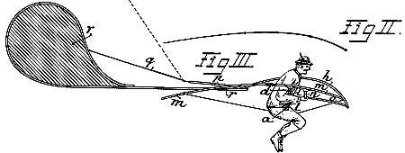
In the accompanying drawings the
flying-machine, constructed according
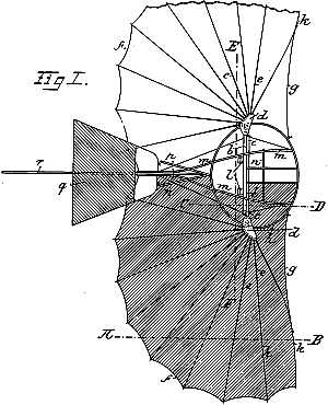
to the present invention, is represented in Figures 1 to 5. Fig. 1
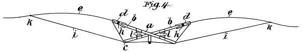
shows a view from above of this flying-machines. Figs. 2, 3, and 4 are
sections on the lines A, B, C, D and E, F of Fig. 1. Fig. 5 shows the
flying-machines when folded up.
In carrying this invention into
practice, two wooden rods a, forming an
acute-angled cross, are arranged to carry at their upper ends b pockets
d, produced
by two small wooden plates. In these pockets are pivoted
the wooden ribs e of the wings. A string f, connecting the
points of
the ribs, and a wire g,
fastened to the first rib of the wing and
hooked to the hoop h,
stretch these ribs in the horizontal direction.
The tension downward is given to the ribs by wires i, which extend
from
the points k
of the lower ends c
of the crossed rods a.
The said hoop l
is nailed, glued, or otherwise secured in the pockets d. With this hoop
are firmly connected the rods m,
to which are attached in front the
wooden bar n,
with the rods o
o, and at
the rear two diverging rods p.
On the latter is pivoted the tail q
such a manner that it can freely
turn upward, but finds downward a point of support on the fixed rudder
r. This
mode of attaching the tail has the advantage that the tail will
have no carrying action when the machine is employed like an ordinary
parachute, thereby preventing the machine from turning over forward.
The rudder r,
which serves for automatically keeping the machine in the
wind's eye, is likewise detachably fastened to the rods m and the hoop
h. The
surfaces of the machine over which fabric is stretched are
shaded in the right-hand half of Fig. 1.
For using this flying-machine the
person inserts his fore-arms between
the cushions l,
fixed to the crossed wooden rods a, Fig. 3, and takes
hold of the bar n
with the hands, so that, without changing the upright
position of his body, he can carry and properly adjust the machine in a
very convenient manner during his run before the flight, while during
the flight he can balance and steer the machine, in which he is
suspended, by a suitable movement of his body, so as to displace its
center of gravity. In this manner he can imitate the so called
"soaring" of birds, in which the movement takes place merely by a
change in the position of the wings with regard to the direction of the
wind, there being no rudder movement proper of the wings. As under
these circumstances the legs are always freely suspended downward the
landing can safely be effected by putting the feet on the ground.
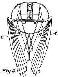 The
folding up of the machine is effected by disengaging the front
tension-wires g
from the hoop h,
turning the ribs about their center in
the pockets d
to the rear and hooking the tension-wires g into the eyes
on the rods m. The apparatus then constitutes a compact whole.
The
folding up of the machine is effected by disengaging the front
tension-wires g
from the hoop h,
turning the ribs about their center in
the pockets d
to the rear and hooking the tension-wires g into the eyes
on the rods m. The apparatus then constitutes a compact whole.
Having now particularly described and
ascertained the nature of my
said invention and in what manner the same is to be performed, I
declare that what I claim, and desire to secure by Letters Patent of
the United States of America, is—
1. In a flying machine, the combination
of two crossed carrying rods a,
two wings vaulted upward, and strings or wires i extending from
the
ends of the carrying rods toward the peripheries of the wings,
substantially as set forth.
2. In a flying machine, the combination
of two crossed carrying rods a,
two wings vaulted upward, strings or wires i connecting the
two
carrying rods with the wings, and a vertical fixed rudder substantially
as set forth.
3. In a flying machine, the combination
of a crossed frame, two wings
connected therewith, strings or wires i, a vertical fixed
rudder r
and
a horizontal tail q,
adapted to turn upward automatically,
substantially as set forth.
4. In a flying machine the combination
with a supporting frame, of a
wing adapted to be folded together and having its ribs diverging from a
common support, and suitably hinged thereto a string connecting the
outer points of the ribs, and continuous fabric attached to a series of
ribs, substantially as set forth.
5. In a flying machine, the combination
with a supporting frame
comprising a hoop, of a wing having its ribs diverging from a common
support, a string connecting the outer points of the ribs, a wire, as
g, fastened to the first rib of the wing and attached to the hoop and
fabric stretched over the ribs and such wire, substantially as set
forth.
6. In a flying machine, the combination
with a supporting frame, of a
wing having its ribs diverging from a common support, fabric stretched
over the ribs and wires, as i, extending from the ribs downward to the
supporting frame for the purpose of adjusting thereby the tension of
the ribs, substantially as set forth.
7. In a flying machine, the combination
with a frame comprising a hoop
and crossed bars connected therewith, of wings supported by said frame,
substantially as set forth.
8. In a flying machine, a supporting
frame for the wings comprising a
hoop h,
rods extending from it for supporting the operator and a tail
and a rudder, and pockets as d
for receiving the ends of the ribs of
the wings, substantially as set forth.
9. In a flying machine the combination
with a supporting frame, of
wings with suitable ribs connected therewith, front tension wires g,
and pockets d for receiving the inner ends of the ribs, the ribs being
made capable of turning around their centers in such pockets for the
purpose of folding up such wings, substantially as set forth.
10. In a flying machine, the
combination with a supporting frame, of
wings, a fixed rudder and a pivoted tail adjusted to come to rest upon
the rudder when swinging downward, substantially as set forth.
Signed at Berlin this 1st day of
February, 1894.
OTTO
LILIENTHAL
Witnesses:
HERMANN
MULLER.
REINHOLD
WEIDNER.