UNITED STATES
PATENT
OFFICE.
CULLEN WHIPPLE,
OF PROVIDENCE, RHODE
ISLAND, ASSIGNOR TO NEW ENGLAND SCREW COMPANY, OF PROVIDENCE, RHODE
ISLAND.
MAKING SCREWS.
Specification
of
Letters Patent No. 15,052,
dated June 3, 1856
To all whom it may concern:
Be it known that I, CULLEN WHIPPLE,
of the city and
county of Providence, in the State of Rhode Island, have invented
certain new and useful Improvements in Machinery for Performing Certain
Parts of the Operations Involved in the Manufacture of Wood-Screws, of
which the following is a full, clear and exact description, reference
being had to the accompanying drawing, which makes part of this
specification, and in which—
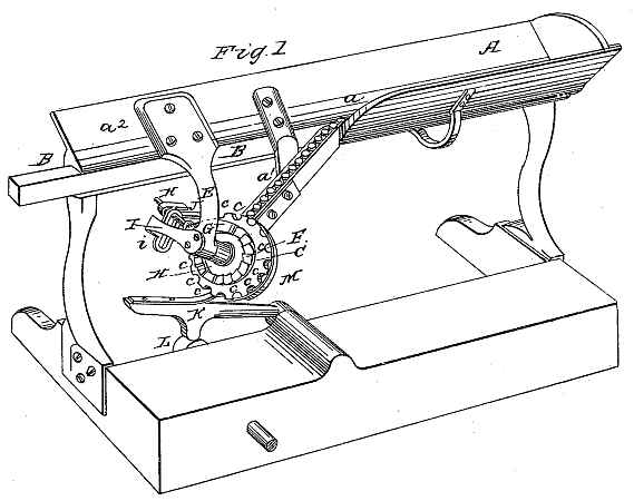
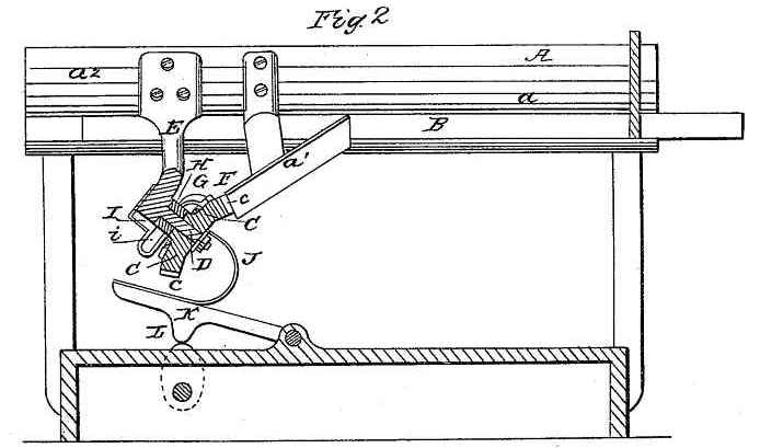
Figure 1. represents a view in
perspective of certain parts of a machine for removing screw blanks
from a heap lying in a hopper in promiscuous order, and arranging them
with their heads all in one direction, and discharging them one at a
time, and at regular intervals, into the feeding pincers, gripping
jaws, or other parts provided for their reception in any of the
machinery employed to perform any of the various operations of making a
screw.
My invention and improvement relate to the feeder for
screw machinery and consist of three elements, viz: 1st, a trough,
slot, channel or other conduit to convey from a heap of screw blanks
lying promiscuously in all positions, a moving row or series of such
blanks with their heads all arranged in the same direction or
thereabouts. 2nd, a series of grooves in a moving surface carried in
succession past the mouth of the conduit in such manner that each
groove will receive therefrom, as it passes, a blank and carry it off.
3rd, a guard, parallel or thereabouts, to the moving surface and placed
against or near the same to prevent the blanks from leaving the grooves
until they reach the point of discharge into the mechanism provided to
receive them.
The accompanying drawing represents a portion of a
frame adapted to machinery for shaving, nicking, or threading screws.
This frame is surmounted by a hopper (A) resting on pedestals, to
receive a quantity of screw blanks in promiscuous order ready to be
arranged with their heads in the same direction.
At the bottom of the hopper a horizontal slot (a) is formed that terminates in a
second slot (a') which
descends at an angle sufficient to permit screw blanks hanging in it by
the head to slide freely through it by their own gravity, in a
direction from its upper toward its lower end. The horizontal slot (a) should have one or both sides
provided with a vibrating bar (B) or roller, or some other contrivance
to move the blanks and cause them to advance slowly toward the inclined
slot (a').
At the lower end of the inclined slot, a frustum of a
cone (C) is placed. It is mounted upon an inclined spindle (D)
supported by a bracket (E) attached to a prolongation (a2)
of one side of the hopper (A). The axis of the frustum is immediately
opposite the mouth or lower extremity of the inclined slot. The
periphery of the frustum has a series of equidistant grooves cut
therein, converging toward the apex of the cone of which the frustum is
a part. These grooves are of a width, measured on the periphery of the
frustum and in the direction of its circumference, equal in width, to
the mouth of the slot, and their depth is nearly but not quite equal to
their width. On the base or larger end of the frustum, an annular
series of equidistant ratchet teeth (F) are formed, which in number are
equal to that of the grooves (c)
in the periphery.
A ratchet hand (G) to act upon the ratchet teeth and move
the frustum (C) is attached to a vibrating arm (H) hinged on the axle
(D) at the inner end, and at the other end guided and supported in a
slot (i) in an auxiliary
bracket (I). The end of the arm (H) projects through the bracket (I) to
connect with the end of a curved link rod (J) which communicates to it
a reciprocating motion. This link rod is attached to a treadle (K)
actuated by a cam (L) on a shaft below. The curved connecting rod is
made of brass, steel, or other material that possesses the required
elasticity, and should be of such a degree of stiffness that it will
without much flexure press the ratchet hand (G) with sufficient force
to turn the frustum, when the same moves freely; and yet at the same
time, it should be so flexible as to yield sufficiently to allow the
treadle to vibrate without moving the frustum, and thus prevent the
machine from being broken in case the turning of the frustum should
become obstructed. At each advance movement of the ratchet hand (G) one
of the grooves (c) in the
periphery of the frustum is brought opposite the mouth of the inclined
slot (a'), and will receive a
screw blank, which will be prevented from falling out of the groove
after it is carried away from the mouth of the slot, by means of a
guard plate (M) which is arranged parallel to the periphery of the
frustum and extends around the same far enough to bring the blanks to
the desired point of delivery. This guard plate (M) may be supported in
one side of the slot, or by any part of the :frame to which it may be
convenient to attach it.
If instead of a frustum of a cone, a cylinder were used,
the heads of the blanks, because of their larger diameter, would have a
constant tendency to roll forward faster than the points, because of
the head of the blank working partially into the space between the
guard plate (M) and the moving surface. The conical form of the
carrying or moving surface counteracts this tendency of one end of the
blank to advance faster than the other, by making the circle in which
the head travels around the base of the frustum longer than that which
the shank has to travel around its apex in the same proportion as that
part of the surface of the head which rolls on the guard plate is
larger in diameter than the part of the surface of the shank which
rolls on the guard plate. By this means the blank has a tendency to
maintain a position parallel to one of the planes radiating from the
axis of the cone. This grooved frustum resembles a beveled cog wheel,
and may be constructed in the same manner.
What I claim as my invention and desire to secure by
Letters Patent, is—
The combination of the feeding slot, (a a') moving series of discharging
grooves, (c), and guard plate
(M); but I make no claim to either of these elements of the combination
by itself. In testimony whereof, I have hereunto subscribed my name.
CULLEN WHIPPLE.
Witnesses:
F. G. FONTAINE,
A. E. H. JOHNSON.