 (source)
|
Luther Crowell
(7 Sep 1840 - 16 Sep 1903)
American inventor whose best-known invention is a machine for making the square-bottomed paper bag. He obtained over 280 patents in his lifetime. His first patent was for an Aerial Machine.
|
To all whom it may concern:
Be it known that I, Luther C. Crowell, of West Dennis, in the county of Barnstable and State of Massachusetts, have invented a new and Improved Aerial Machine; and I do hereby declare that the following is a full, clear, and exact description of the same, reference being bad to the accompanying drawings, forming a part of this specification, in which—
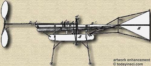
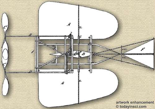
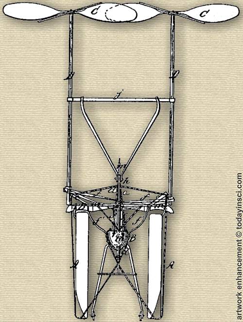
Figure 1 represents a side elevation of my invention. Fig. 2 is a plan or top view of the same. Fig. 3 is a front elevation of the same.
Similar letters of reference in the three views indicate corresponding parts.
This invention consists in the arrangement of two or more flat sharp-pointed hinged wings capable of being turned up into a horizontal position or down into a vertical position and of one or more rotary hinged propellers the shafts of which can be brought in a horizontal or in a vertical position or to any desired inclination, in combination with a pyramidal winged steering apparatus or rudder and with a suitable car, in such a manner that from said car the motion of the whole machine can be controlled by the position given to the propellers, to the wings, and to the rudder.
To enable others skilled in the art to make and use my invention, I will proceed to describe its construction and operation with reference to the drawings.
The wings A are composed of a light substantial frame work of wood or any other suitable material covered with oiled cloth or silk or other material impervious to air or gas, and they are so arranged that there will be a space of two or three feet between the top and bottom coverings. When the machine is to be used, this space is filled with hydrogen or other suitable gas. The wings are hinged to the frame work B' by means of loops and eyes or in other convenient manner, so that they can lie turned down into a vertical position, as shown in Fig. 3, or up into a horizontal position, as shown in Figs. 1 and 2, their position being adjusted by means of ropes a b, which are firmly attached to the outer edges of the wings, the ropes a passing through arms c, that are fastened to the frame work B', and over a standard, d, down to the car B, and the ropes b passing from the edge of the wings direct to a standard, e, and thence to the interior of the car.
The car B is connected to the frame-work B' by means of hinges or pendants f', and it contains the engine, the operators, and, in fact, everything intended to be carried up in the aerial machine. It is constructed of such material as combines strength with lightness and its size is in proportion to the size of the wings. The standard d, which supports the ropes a for turning, the wings up into a horizontal position, rises from the upper surface of car B, and the standard c, which supports the ropes b for turning the wings down in a vertical position, projects from the lower surface of said car, and the ropes a b are attached to a suitable windlass or windlasses in the interior of the car for the purpose of adjusting the position of the wings.
C C are the propellers, which are intended to revolve in opposite directions, and which are attached to the outer ends of shafts D. A rotary motion is imparted to these shafts by means of linked bands or chains f, passing from the main wheel in the interior of the car over a drum, g, that has its bearings in suitable cross-bars in the frame-work B', and from that drum over pulleys or chain-wheels h at the inner ends of the propeller-shafts. The bearings of said shafts are so arranged that the shafts can be turned down in a horizontal or up in a vertical position without interrupting their rotary motion. This object is effected by making the bearings near to their inner ends in boxes i, which are hinged to one of the cross-bars of the frame work B', and the other bearings of said shafts are in the ends of an arm or cross-bar, j, which forms a portion of a derrick or lever frame, j k, that serves also to raise or lower the propeller shafts with the propellers. The inner end, k of the derrick j k connects by a rope, l, with a suitable windlass in the interior of the ear in such a manner that by the action of said windlass and rope the propeller-shafts can be raised or lowered at pleasure.
For the purpose of steering the machine a winged pyramidal rudder, F, is suspended from the rear end of the frame-work B', and said, rudder is provided with four cross-shaped arms, m, from which cords or lines extend to the interior of the car for the purpose of adjusting the position of the rudder.
In order to preserve the water, the exhaust-steam from the interior of the car maybe carried through a longed curved pipe outside the car, so that the same condenses readily either in the pipe or in the feed-water tank, or it may be condensed in any other desirable manner. When it is desired to ascend with this machine and to carry up a certain load or weight, the wings are turned down to the position shown in Fig. 3 of the drawings, and the propeller-shafts are turned up in a vertical direction, and when the desired height is attained and it is desired to progress in a horizontal direction the wings are raised and the propellers lowered to the position shown in Figs. 1 and 2.
When it is desired to employ this aerial machine as an engine of war, it could be elevated, loaded with shell, and when arrived over the desired spot the shell could be discharged.
Having thus fully described my invention, what I claim as new, and desire to secure by Letters Patent, is—
The arrangement of the hinged wings A, car B, and pyramidal winged steering apparatus or rudder E, in combination with the adjustable hinged propellers C, constructed and operating substantially in the manner and for the purpose herein shown and described.
Zadak Crowell.
- 7 Sep - short biography, births, deaths and events on date of Crowell's birth.
- Luther Childs Crowell - Biography of the Cape Cod Inventor of the Square-Bottom Paper Bag Machine.


